Get reliable precision with S. Himmelstein’s thrustmeters, expertly designed for accurate measurement of axial force in a wide range of industrial and research applications. Our thrustmeters provide highly dependable performance, making them ideal for industries such as aerospace, automotive, oil & gas, and electric motors. Built for accuracy, these torque sensors deliver real-time thrust data that helps optimize operations, improve efficiency, and enhance product quality.
Torque Gauges & Meters
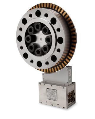
MCRT® 94000V Thrustmeters have high accuracy in real-world applications, not just in the cal lab. That’s due in part to 200% Thrust Overload1 with 200% Electrical Overrange1 Ratings which combined avoid and/or greatly reduce errors from clipped thrust peaks. Also contributing to their outstanding performance are very low errors from torque crosstalk; most practical applications have high Torque to Thrust ratios making this a critical, real world feature. Industries highest Thrust to Torque Ratios combined with low Torque crosstalk make this product the best choice for rotary Thrustmeters.
A drift free Carrier Amplifier, immune to dc, ac power line and most ac noise, handles the thrust bridge output. Hardening against EMI from VFDs and other industrial noise sources further enhances performance.
Bi-directional rotor shunt cal verifies calibration and operation of the entire data chain in both Tension and Compression.
Combined Error is ≤0.05% to ≤0.8% as listed for the Sensors’ Performance Grade. Torque Crosstalk Errors are as low as ≤0.2%, grade dependent. Every Model is shipped with an ISO/ IEC 17025:2017 Accredited Calibration. These Thrustmeters won’t yield when subjected to forces or torques equal or less than their Overload Rating. They have infinite fatigue life for full reversals up to half their Overload Rating. Installed with a shaft coupling, the result is a short stiff driveline, with low overhung moment. A Speed signal is optional.
The thrust signal is digitized on the rotor and sent to the stator without contact, where analog, frequency and Com Port outputs are created. Included software interfaces with your Windows-based PC. Use RS232, 422, or 485 digital communication. Display Real-time, Max/Min, and Spread Thrust, Rotor Temperature, do limit checks, real-time plots and save data. Password protection may be invoked.
WHY USE MCRT® 94000V ROTATING THRUSTMETERS
Unmatched Precision in the Real World and in the Cal Lab
- Combined Error ≤0.05% tested and documented to Rated Thrust. Combined errors based on both a reference line that most closely matches the sensor’s performance (CE-BFL) and one (SEB) where the reference is passed through the zero load point are documented. SEB (Static Error Band) is commonly used for load cells and in Europe. We prefer the Best Fit Line (CE-BFL) because it most closely matches the sensor’s performance. Both are calculated from the same accredited Thrust data and documented for this product.
- Torque Crosstalk ≤0.2% tested and documented to Rated Torque. Virtually all practical applications have high Torque to Thrust ratios. Consider a centrifugal pump test. The pump’s torque in lbf-in is invariably greater than its Thrust in lbf. Torque is crucial in developing the pump’s output and to its efficiency whereas Thrust isn’t. Nonetheless, it’s important to verify Thrust loads to confirm Thrust bearings and related components are adequately sized. Clearly Torque Crosstalk must be low to avoid significant Thrust errors and faulty conclusions based on them. MCRT® 94000V Thrustmeters are unsurpassed for low Torque Crosstalk which is conservatively specified under realistic worst case conditions, i.e., with Maximum Rated Torque applied.
- High precision extends a sensor’s low range usefulness. Compare 0.1% and 0.01% devices with the same full scale. The more accurate device will have one tenth the error of the other. Therefore, it will satisfy a test need that is ten times as stringent as the other. Accordingly, a single High Accuracy meter is frequently used instead of multiple lower accuracy meters.
- High Electrical Overrange assures Thrust measurements between Rated Thrust and Overrange Thrust are correctly reported. Electrical Overrange is 200% of Rated Thrust on the digital output even with maximum torque applied; with low torques it is 300%. On the analog output, data is correct to 150% of Rated Thrust with the analog output set at 10V full scale or 200% when set to 5V full scale. In any case, errors from clipped thrust peaks, when present, are eliminated or significantly reduced in a sensor with high Electrical Overrange and high Mechanical Overload.
- A Drift Free Carrier Amplifier conditions the strain gage thrust bridge. It is immune to thermocouple signals, power line and most ac noise sources.
- 0.001%/°F Temperature Compensation is consistent with the excellent overall sensor performance.
- A Documented ISO/IEC 17025: 2017 Calibration is provided with every sensor. It is referenced to a bi-directional rotor bridge shunt. Competitors only offer a Uni-directional bridge shunt which limits field verification and adjustments to one direction, tension or compression. Himmelstein sensors come with an ISO/IEC 17025 accredited calibration whereas most competitors impose a surcharge for one.
Unmatched Safety Margins
- A 200% Thrust Overload Rating is standard and provides added protection during use. High Overload combined with High Overrange means most data above full scale is valid, or its error is reduced due to combined high overload and overrange capabilities.
- Infinite Fatigue Life for Full Reversals to Half the Overload Rating is standard.
- Sensors are safe for life and fatigue testing.
- Extraneous Load Ratings apply without derating the Thrust capacity as required by most other sensor makers. That provides enhanced safety margins and increases test flexibility.
Valuable Data Processing Features
- Correctly computes and updates Shaft Thrust before filtering dynamic components.
- Samples Shaft Thrust 20,000 times/second and Outputs it in analog, digital and frequency form.
- Updates the Maximum and Minimum Value of Thrust 20,000 times/second.
- Updates Data Spread (Max. - Min.) of Thrust 20,000 times/ second.
- Has 14 Bessel Data Filters for Thrust, selectable from 0.1 to 3,000 Hz in 14 steps without a need to re-calibrate.
- Supports 11 Engineering Units of Measure without a need to re-calibrate.
Simple to Install and Operate
- Readily achievable installed Axial and Radial Rotor Runout (0.002"). Competitive bearingless sensors require a tighter runout that is more difficult to achieve and maintain under field conditions.
- Generous rotor-to-stator air gaps simplify installation and reduce chances of a collision.
- Rotors are installed without special fixtures or alignment tools.
- Neither a Hoop nor a Caliper Antenna is used, simplifying installation, and reducing the chance of a collision.
Trust S. Himmelstein for Thrustmeters
Using an MCRT® 94000V, you benefit from our more than six decades of experience singularly focused on designing, making, and supporting the most accurate, most reliable, easiest to use non-contact rotary sensors, bar none.
EASY INSTALLATION, HIGH OPERATING EFFICIENCY
These Bearingless Thrust Sensors have neither hoop nor caliper stator antenna nor do they have critical mounting restrictions. What is more, they provide generous rotor-to-stator clearances (see specification). These characteristics yield easy user installation without the need for special alignment tools. Their allowable clearances accommodate significant thermal and other growths which are often encountered in the field, particularly in continuous duty applications.
Rotor-to-Stator Gap Specifications are all inclusive. That is, and MCRT®94000V may be operated anywhere within the envelope defined by their axial and radial gap specifications.
The Standard product employs an optical speed sensor (option O). It tolerates very wide axial rotor-to-stator gaps. Its output is a TTL pulse train whose frequency is directly proportional to shaft speed.
The antenna and electronic circuit design boasts world class efficiency. For example, even at their more generous gap extremes the power needed to operate the antenna system and standard electronics is less than that needed for most competitive devices. That despite the fact these products contain data processing functions not found in those other devices.
FAQs
How do thrustmeters handle torque crosstalk?
Himmelstein thrustmeters are engineered to minimize torque crosstalk errors, ensuring highly accurate thrust measurements even when torque loads are present.
What are the benefits of the drift-free carrier amplifier?
It enhances signal stability by resisting interference from DC, AC, and other electrical noise, contributing to reliable thrust measurements.
What output options are available for thrustmeters?
Thrustmeters provide analog, frequency, and Com Port outputs, along with optional RS232, RS422, or RS485 communication for compatibility with modern systems.